How to Select the Right Drive for Automated Vehicles
From Bruce Dern in Silent Running, to Arnold Schwarzenegger in the Terminator series, to Will Smith in I Robot, we see Hollywood’s idea of automated machines taking over the work of humans, often against our will. But move over Mr. Schwarzenegger: the rise of the real machines is upon us.
Real machines are designed for practical, useful work -- not for taking over the world. In the past decade alone we have witnessed a wave of intelligent mobile machines introduced into the market, designed specifically to help (or replace) humans in a tremendous number of activities.
In fact, Oxford University researchers have estimated that 47 percent of U.S. jobs could be automated within the next two decades. To help engineers understand how to select the right drives to power their automated vehicles, we put together the following guide.
Automated vehicles: Making life easier
A convergence of improved technologies, such as better batteries, more efficient motors, GPS, RFID and laser guidance systems, and increasingly powerful microcontrollers, has enabled the design of evermore capable automated vehicles.
Set-piece robots in manufacturing are not new. What is new, however, are smaller, cost-effective mobile robotic vehicles and assistive machines that assist with many of the more mundane, repetitive, expensive and dangerous tasks normally performed by humans, such as:
- Cleaning
- Lifting
- Stacking
- Carting
- Transporting
- Diffusing bombs
When used in a warehouse, for example, robots can improve productivity by over 800 percent. This, of course, occurs because robots can move faster than humans (without tiring), and because the automated systems eliminate human error.
Powering automated vehicles with electric motors
By definition, vehicles move, meaning they require some means to cause movement. In the case of electrically powered vehicles that is normally an electric motor connected through a gear train to one or more drive wheels or treads. Typically, these vehicles are battery powered, and some are intelligent enough to go plug themselves in at a charging station when they need to.
There is an expanding market for such vehicles -- the global mobile robotics market is expected to grow by 12.6 percent by 2019. This is the result of a combination of new technology and the desire for lean and green practices adopted by management teams throughout the industry.
The names applied to the types of vehicles in these studies are many, such as:
- AGVs
- AGCs
- Unit load vehicles
- Electric carts
- Tuggers
- Pushers
Overall, their defining characteristics are mobile, intelligent (in many cases), semi- or fully-autonomous, and often electrically powered.
Understanding vehicle loads and drive systems
The size of the market for such vehicles could range today more than $750M. The market narrows somewhat when you segregate by load: previous studies separate unit load vehicles at 10,000 lbs. (4,500 kg) and under with heavier loads left to the fork truck manufacturers of the world.
The category of vehicles of interest here are those designed to handle up to 10,000 lbs. (4,500 kg). These machines range from the simple material handling robots that may cost less than $1,000 to programmable, fully-automated AGVs costing in excess of $50,000. But, even a range of 100 lbs. (45 kg) to 10,000 lbs. (4,500 kg) is too broad when considering workloads handled by one, two or a few humans.
Such tasks can usually be handled by vehicles rated for loads up to about 2,000 lbs. (900 kg):
- Construction site material movement
- Stockroom product handling
- Hospital patient transportation and handling
- Delivering meals, linens or medications
- Moving heavy diagnostic equipment
We’ll look at electrically powered vehicles in this load class of about 100 lbs. (45 kg) up to 2,000 lbs. (900 kg), and in particular the types of propulsion systems used in them, including fully integrated traction drive systems.
Selecting the right electric vehicle propulsion design
There are two basic approaches to electric vehicle propulsion design.

In-wheel designs
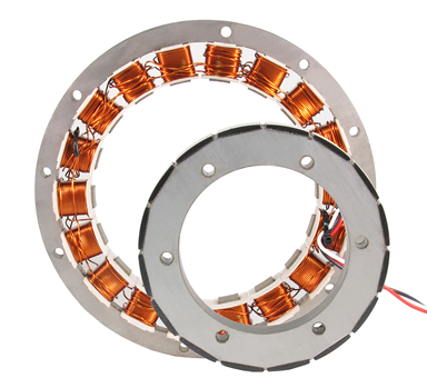
This concept was actually first introduced more than a century ago for use in automobiles. Recent technology advancements have made in-wheel propulsion drives a viable alternative for applications requiring a compact, quiet solution. This type of drive system consists of an electric motor designed to fit within the confines of a vehicle’s wheel rim.
The rotating component of the motor is directly integrated into the rim and applies torque directly to the wheel. Without any mechanical advantage (gearing), the motor needs to produce higher torque levels than geared solutions, and do it at relatively lower speeds. Unless the motor is properly designed, it will have poor efficiency in the typical operating range for direct-drive, in-wheel solutions.
Torque motors are generally the preferred choice for in-wheel designs. Component count is significantly less than other solutions because no gear trains are used. This also means that there’s no gear power loss.
Other benefits of in-wheel designs include:
- Efficiencies of more than 80 percent have been realized with in-wheel propulsion systems. High efficiency is, of course, very important for battery powered vehicles.
- In-wheel solutions can result in more compact, space-saving designs than other approaches.
- Where low audible noise is an issue, no other solution beats the direct-drive design.
Challenges remain for direct-drive, in-wheel solutions, however. The high torque motors required are more expensive than traditional electric motors, and may even be more expensive compared to a motor and drivetrain combination that produces the same performance. Also, an in-wheel motor is exposed to the same environment as the wheel itself, so care must be taken to engineer adequate protection.
Off-Wheel Designs
Off-wheel designs, where one or more electric motors transmit power to the drive wheels through a drivetrain, are currently more common than in-wheel designs. The most common drivetrains used include belt and pulley, chain and sprocket, and various types of gearboxes. Some designs use a combination of these transmissions.
The mechanical advantage of the drivetrain reduces the torque required from the motor, but increases the speed of the motor proportionately. A more economical electric motor can be used, but the cost of the drivetrain may result in little savings when comparing geared off-wheel with direct-drive in-wheel solutions.
Off-wheel designs do have advantages compared to in-wheel designs:
- There are more package size and configuration options available because there aren’t the space constraints of an in-wheel design to deal with.
- A smaller diameter wheel is possible, where an appropriately-sized direct-drive motor design typically dictates the wheel size
- It’s generally much easier to add accessories to off-wheel motors such as encoders, holding brakes and integrated electronic drives.
- The vehicle frame may offer protection for the motor, electronics and drivetrain from a harsh environment.
On the down side, off-wheel designs don’t compare favorably with in-wheel designs on efficiency measures. Further, reliability will be lower and audible noise higher because of the added complexity of the gearing compared to in-wheel solutions.
How to size a wheel drive for applications

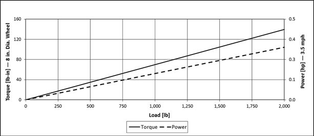
Figure 1: Required torque and power from an eight-inch WheelMax running on a typical flat surface over a range of loads.
There are a number of considerations that need to be taken into account to properly size a wheel drive for an application:
- The foremost is the total weight of the loaded vehicle and how many drive wheels the vehicle will have. The load to be handled by each wheel drive is then roughly the total weight divided by the number of drive wheels. If unpowered casters are used in addition, the normal load each wheel drive must handle will be less, but not the inertial mass that each wheel drive sees when accelerating.
- Acceleration torque delivered by the wheel may need to be several times larger than the torque needed to maintain speed or even to climb a ramp. Note that rated performance for a wheel drive is dependent upon other operating conditions such as incline angles that must be negotiated.
- Wheel drive diameter influences the torque level and speed required from the wheel to achieve a given performance level for the vehicle. Larger wheel diameters may be necessary to meet ground clearance and/or speed requirements, and they can provide smoother travel on rough surfaces, but they also require more motor torque.
On the plus side, the required motor speed and power are less with a larger diameter wheel. As an example, Figure 1 illustrates the torque and power required of an eight-inch wheel drive operating on a flat surface over a range of loads.
The WheelMax: Offering the best of both worlds

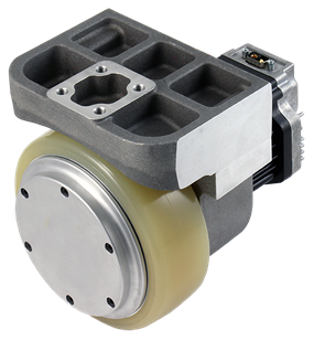
Figure 2: 152 mm (6-inch) WheelMax wheel drive
Allied Motion has recently introduced the WheelMax, a new powered electric wheel drive with integrated drive electronics. The WheelMax offers benefits similar to those of an in-wheel, direct-drive design, but, in fact, is an off-wheel design. The first available models are the GWM-5257 and GWM-5267.
These wheel drives each incorporate an Allied Motion brushless DC EnduraMax motor coupled to the wheel through an efficient two-stage helical, epicyclic gearbox that is integral to the wheel drive’s housing. The assembly also includes a mounting bracket. A six- or eight-inch urethane tire completes the assembly.
Gear design and geometry in this drive wheel have been optimized to reduce noise and vibration and improve gear life. Units have been tested under elevated temperatures and in high impact emergency stop conditions -- performing beyond expectations.
The WheelMax’s integrated EnduraMax brushless motor includes an integral electronic drive to power the motor and control a holding brake when that option is present. And, of course, there is no need for regular brush replacement with the brushless EnduraMax motor.
The GWM wheel drives are typically used in pairs on AGV/AGC and similar electric utility vehicles to transport a wide range of load types up to 2,000 lbs (908 kg) in total weight. The WheelMax’s modular mounting bracket is designed to be easily customized to accommodate a variety of vehicle mounts.
Table 1 below summarizes the basic data for the GWM line of wheel drives. More information and the full datasheet for the GWM series are available here.
Table 1: WheelMax Characteristics
| Series | Rated Load Capacity | Tire Diameter | Rated Wheel Speed | Winding Voltage | Rated Output Torque | Rated Output Power |
| (kg) | (mm) | (RPM) | (VDC) | (Nm) | (W) | |
| GWM-5257 | 227 | 152 | 160 | 24, 48 | 8.6 | 246 |
| GWM-5267 | 454 | 203 | 102 | 24, 48 | 21 | 350 |
Picking the right wheel drive for your vehicle
A full analysis of a wheel drive’s required performance, including peak torque for acceleration and average power needed for typical vehicle travel routines, is needed in order to choose the best wheel drive for an application.
The terrain the vehicle will travel must be factored in as well. Vehicles that must negotiate steep inclines or run on surfaces with a high rolling resistance, such as carpet, will require a motor with greater torque capacity.
Because of these varying vehicle requirements, Allied Motion assists our customers in analyzing their application in order to ensure that all operating conditions are considered and met.
Have questions on wheel drives or the WheelMax? Contact us or connect with us on Twitter @AlliedMotion1.
